Free workshop on ETABS
Detailed Course Plan for ETABS
Total Course Duration: 40 Hours
Total Number of Classes: 20
Duration Per Class: 2 Hours
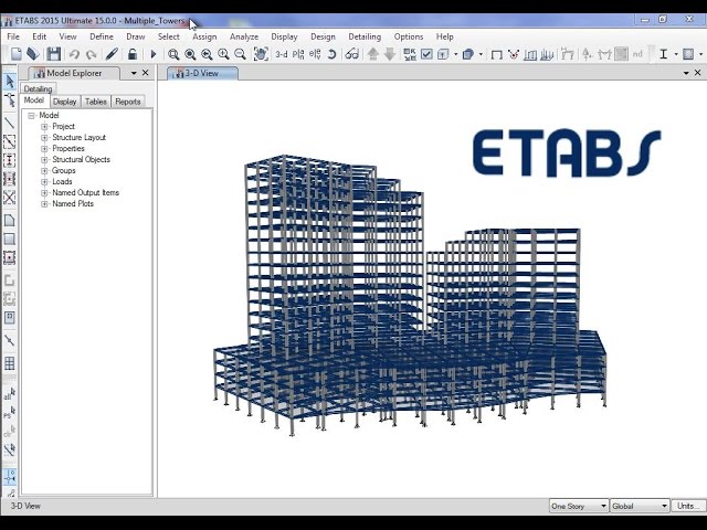
Class 1. Introduction to ETABS
o Overview of software capabilities, applications, and interface navigation.
o Project planning: understanding building types and structural systems.
Overview of Software Capabilities and Applications
Capabilities: ETABS is tailored for structural analysis and design of buildings. It
integrates 3D modeling, analysis, and design into one software, offering features like
dynamic analysis, load application, and code-based design checks.
Applications: Ideal for high-rise buildings, bridges, and industrial structures. Common
uses include designing reinforced concrete, steel, and composite structures.
Interface Navigation
Familiarize with menus, toolbars, and workspace.
Understand key sections: model explorer, graphical viewports, and output windows.
Customize interface for efficient workflow.
Project Planning
Identify building type (e.g., commercial, residential, industrial).
Define structural systems: moment frames, shear walls, braced frames, or hybrid systems.
Discuss key design considerations: gravity loads, lateral forces, and material specifications.
Class 2. Creating Grids and Story Definitions
o Defining grids, story levels, and basic geometry setup.
o Introducing model views and story-specific settings.
Defining Grids
Importance of grids for precision in modeling.
Customize grid spacing based on structural layout (e.g., 5x5m grid for offices).
Label axes (X, Y, Z) and modify the grid for irregular shapes.
Story Levels
Define levels based on floor heights and building type.
Assign varying story heights (e.g., 3m for residential, 4m for commercial).
Link story data to structural elements like beams, columns, and slabs.
Geometry Setup
Place initial components: columns, walls, and slabs.
Visualize and adjust geometry using the 3D graphical workspace.
Model Views and Story-Specific Settings
Switch between plan, elevation, and 3D views.
Define specific settings for each story (e.g., different wall thicknesses or material
properties).
Enable/disable diaphragms for flexible or rigid floors.
Class 3. Frame Property Specifications
o Assigning properties for beams, columns, and braces.
o Material selection: concrete and steel options.
Assigning Properties for Beams, Columns, and Braces
Beams: Define dimensions, cross-sectional shapes (e.g., rectangular, I-section), and assign
material properties (e.g., concrete grade, steel type).
Columns: Input column dimensions and material properties to resist axial and bending
forces.
Braces: Assign diagonal brace properties for lateral stability. Define cross-sectional shape
and connection types.
Material Selection
Concrete: Choose compressive strength grade, density, and modulus of elasticity.
Steel: Assign yield strength, ultimate strength, and elasticity parameters.
Apply predefined or user-defined material libraries.
Class 4. Shell Property Specifications
o Defining and assigning slab, wall, and diaphragm properties.
o Modeling various shell element configurations.
Defining and Assigning Slab, Wall, and Diaphragm Properties
Slabs: Specify slab thickness, material, and load distribution (e.g., one-way, two-way).
Walls: Define wall thickness, stiffness, and reinforcement ratios for structural or nonstructural
walls.
Diaphragms: Assign rigid or semi-rigid diaphragm properties for lateral load distribution.
Modeling Various Shell Element Configurations
Use shell elements to model curved, inclined, or irregular surfaces.
Subdivide shell elements for finer mesh in complex regions.
Class 5. Joint Property Specifications
o Setting boundary conditions, supports, and hinges.
o Applying joint restraints and monitoring displacements.
Setting Boundary Conditions, Supports, and Hinges
Define fixed, pinned, or roller supports at base nodes.
Introduce hinges for rotational freedom in beams or braces.
Applying Joint Restraints and Monitoring Displacements
Restrict node movements for stability.
Monitor critical joint displacements to assess structural performance under loads.
Class 6. Defining and Assigning Loads
o Gravity loads: dead and live loads.
o Environmental loads: wind and seismic (static cases).
Gravity Loads: Dead and Live Loads
Dead Loads: Constant loads like the weight of the structure itself (beams, slabs, etc.).
Assign using standard material weights or manual input.
Live Loads: Variable loads (e.g., occupancy, furniture) typically specified by building
codes or design standards for specific building types (residential, office, etc.).
Environmental Loads: Wind and Seismic (Static Cases)
Wind Loads: Use code-based procedures to calculate wind forces on the structure
depending on the location, building height, and shape.
Seismic Loads: Apply based on the seismic zone and building design category, using static
or dynamic methods for analysis.
Class 7. Load Combinations and Analysis Settings
o Defining load combinations per building codes.
o Setting up linear and nonlinear static analysis.
Defining Load Combinations per Building Codes
Specify different load combinations according to the relevant local or international building
codes (e.g., ASCE, Eurocode, IS 456).
Combinations account for safety factors, using dead, live, wind, and seismic loads together
to simulate real-life loading conditions.
Setting up Linear and Nonlinear Static Analysis
Linear Static Analysis: Assumes material behavior remains linear, and deformations are
small (used for most standard designs).
Nonlinear Static Analysis: Used for complex or highly nonlinear behavior (e.g., plastic
deformation, large displacements). Set up using appropriate material models and nonlinear
load paths.
Class 8. Concrete Frame Design
o Designing beams and columns for concrete structures.
o Exploring rebar layouts and code compliance checks.
Designing Beams and Columns for Concrete Structures
Use ETABS to design reinforced concrete beams and columns to meet strength,
serviceability, and stability requirements.
Perform checks for bending, shear, axial load, and torsion according to the relevant code
(e.g., ACI, IS 456).
Exploring Rebar Layouts and Code Compliance Checks
Define rebar layouts in concrete elements, considering spacing and coverage.
Verify compliance with code standards for minimum reinforcement, bar diameters, and
spacing.
Class 9. Detailing for Concrete Components
o Reviewing design outputs and editing reinforcement details.
o Generating drawings and exporting reinforcement schedules.
Reviewing Design Outputs and Editing Reinforcement Details
Review design results for reinforcement quantity, location, and sizing.
Edit reinforcement to meet local regulations and practical constraints.
Generating Drawings and Exporting Reinforcement Schedules
Create detailed construction drawings of reinforced concrete elements.
Export reinforcement schedules for fabrication, providing complete details of the layout,
size, and number of bars.
Class 10. Steel Frame Design
o Designing structural steel components, including columns and beams.
o Using automated design checks against code specifications.
Designing Structural Steel Components (Columns and Beams)
Use ETABS to model and design steel components like beams, columns, and braces.
Design elements to meet strength and serviceability requirements using the appropriate
steel section (e.g., I-beams, channels).
Consider factors such as axial load, bending, shear, and stability for column design.
Automated Design Checks Against Code Specifications
ETABS automatically performs design checks according to relevant steel design codes
(e.g., AISC, Eurocode).
The software verifies that all elements satisfy the necessary strength and stability
requirements.
Class 11. Steel Connection Design
o Assigning connection types and detailing steel joints.
o Validating connection designs per code requirements.
Assigning Connection Types and Detailing Steel Joints
Select connection types (e.g., bolted, welded) based on structural requirements.
Define joint configurations for beam-column, beam-to-beam, and column-to-foundation
connections.
Assign connection properties such as bolt sizes and weld types.
Validating Connection Designs Per Code Requirements
ETABS evaluates connections against local codes and standards (e.g., AISC, Eurocode).
The program ensures that all joints are structurally sound and meet design criteria for
strength, stiffness, and safety.
Class 12. Steel Joist Design
o Modeling composite steel joists for lightweight structures.
o Exploring pre-defined joist properties and customizing.
Modeling Composite Steel Joists for Lightweight Structures
Use composite steel joists for efficient design in lighter structures.
Model joist properties like span lengths, loadings, and spacing for accurate analysis.
Exploring Pre-Defined Joist Properties and Customizing
ETABS offers predefined joist properties based on common steel joist specifications.
Users can customize these properties for specific project requirements, such as joist depth,
material type, and spacing.
Class 13. Composite Beam Design
o Defining composite beam sections and properties.
o Performing checks for load capacity and deflections.
Defining Composite Beam Sections and Properties
Composite beams combine steel and concrete elements, which ETABS can model
accurately.
Define the section properties (e.g., beam depth, flange width, reinforcement) to ensure
optimal performance.
Performing Checks for Load Capacity and Deflections
ETABS performs structural analysis on composite beams to check for strength,
serviceability, and deflection limits.
The design checks are done according to relevant standards and ensure the beam is safe
under expected loads.
Class 14. Modeling Shear Walls and Diaphragms
o Advanced shell modeling for lateral load resistance.
o Assigning diaphragms for rigid/flexible floor behavior.
Advanced Shell Modeling for Lateral Load Resistance
Use shell elements to model shear walls and diaphragms for lateral load resistance.
Define material properties and assign boundary conditions to simulate the structural
behavior under lateral forces such as wind or seismic loads.
Assigning Diaphragms for Rigid/Flexible Floor Behavior
Assign rigid or flexible diaphragm properties based on the floor system's behavior.
Consider the effects of diaphragm flexibility in multi-story buildings, particularly in
seismic or wind load analysis.
Class 15. Dynamic Analysis: Modal and Time History
o Understanding dynamic properties of structures.
o Modal and time history analysis setup.
Understanding Dynamic Properties of Structures
Investigate the dynamic behavior of structures under time-varying loads.
Study natural frequencies, mode shapes, and damping characteristics essential for seismic
and vibration analysis.
Modal and Time History Analysis Setup
Set up modal analysis to determine the vibration modes of the structure.
Configure time history analysis for assessing the impact of dynamic loads (e.g.,
earthquakes) on the structure over time.
Class 16. Seismic Analysis
o Defining response spectrum functions.
o Simulating seismic effects on multi-story buildings.
Defining Response Spectrum Functions
Define seismic response spectrum functions based on the region's seismic code (e.g., IS
1893, ASCE 7).
Use the spectrum to capture the dynamic response of the structure during an earthquake.
Simulating Seismic Effects on Multi-Story Buildings
Apply seismic loads to multi-story buildings, considering their mass distribution, stiffness,
and damping.
Analyze the structural behavior under seismic forces, checking for displacement, drift, and
stability.
Class 17. Wind Load Analysis
o Defining wind loads and applying to structural models.
o Reviewing analysis outputs for stability and drift.
Defining Wind Loads and Applying to Structural Models
Define wind load parameters (e.g., velocity pressure, exposure factor) according to relevant
codes.
Apply these loads to the structural model based on the building’s location, shape, and
height.
Reviewing Analysis Outputs for Stability and Drift
Assess the building's stability by reviewing displacement and drift under wind loads.
Check the deflections and ensure the building meets serviceability limits to prevent
discomfort or damage.
Class 18. Troubleshooting and Optimization
o Identifying common modeling errors.
o Optimizing designs for cost and material efficiency.
Identifying Common Modeling Errors
Learn how to detect common modeling mistakes, such as incorrect boundary conditions,
improper material assignments, or geometry errors.
Use diagnostic tools and error-checking methods in ETABS to ensure the model is set up
correctly before analysis.
Optimizing Designs for Cost and Material Efficiency
Explore methods for optimizing the design of structural elements to reduce material use
while maintaining safety and performance.
Focus on beam and column sizing, reinforcement layouts, and connection design.
Class 19. Report Generation and Documentation
o Creating detailed calculation reports and export options.
o Preparing drawings and project documentation.
Creating Detailed Calculation Reports and Export Options
Learn how to generate detailed calculation reports from ETABS, which include all design
checks, load combinations, and analysis results.
Understand the different export options available for documentation purposes (e.g., Excel,
PDF, Word).
Preparing Drawings and Project Documentation
Generate construction drawings directly from the model, including plan views, elevation
views, and reinforcement details.
Prepare project documentation that includes structural analysis, design calculations, and
code compliance.
Class20. Final Project and Presentation
o Completing a full-scale ETABS model.
o Presenting project results with peer and instructor feedback.
Completing a Full-Scale ETABS Model
Apply all skills learned throughout the course to complete a full-scale ETABS model of a
building or structure.
Incorporate all elements, including loadings, analysis, design, and detailing.
Presenting Project Results with Peer and Instructor Feedback
Present the final project to peers and instructors, discussing design decisions, challenges
faced, and how the software was used to resolve them.
Receive feedback for further improvement and understanding of ETABS applications.

No Review Found
No Comments Found
The course objective is to train the students on creating effective 3D modeling, interior & exterior building designs and the..